Control units/ Vehicle control

Transmission & Vehicle Control Unit

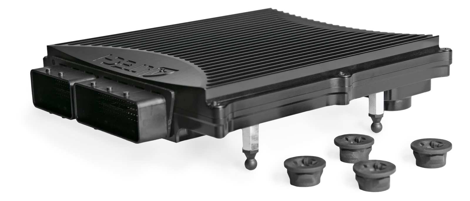
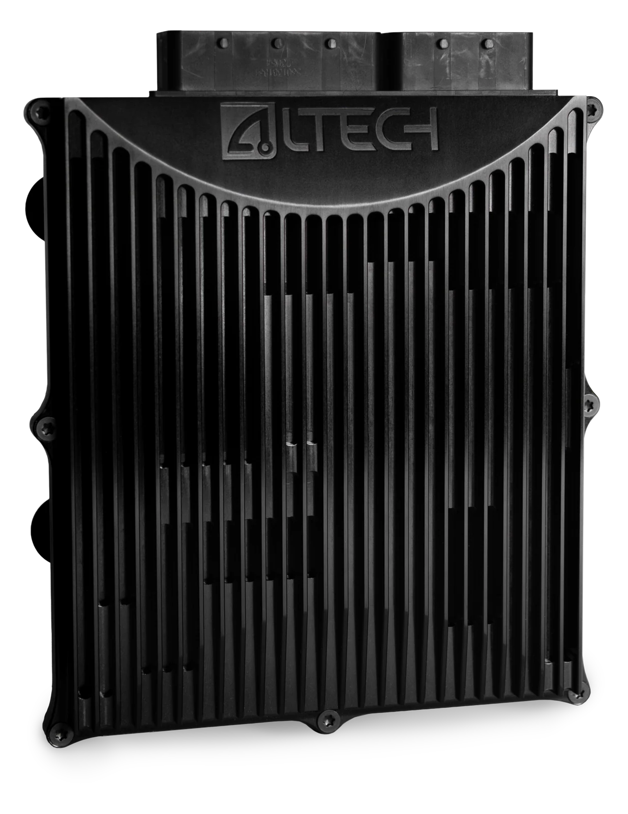
A combined unit for transmission control and vehicle-level torque and powertrain coordination. Separate execution units and an external supervisor keep it safe without giving up speed.
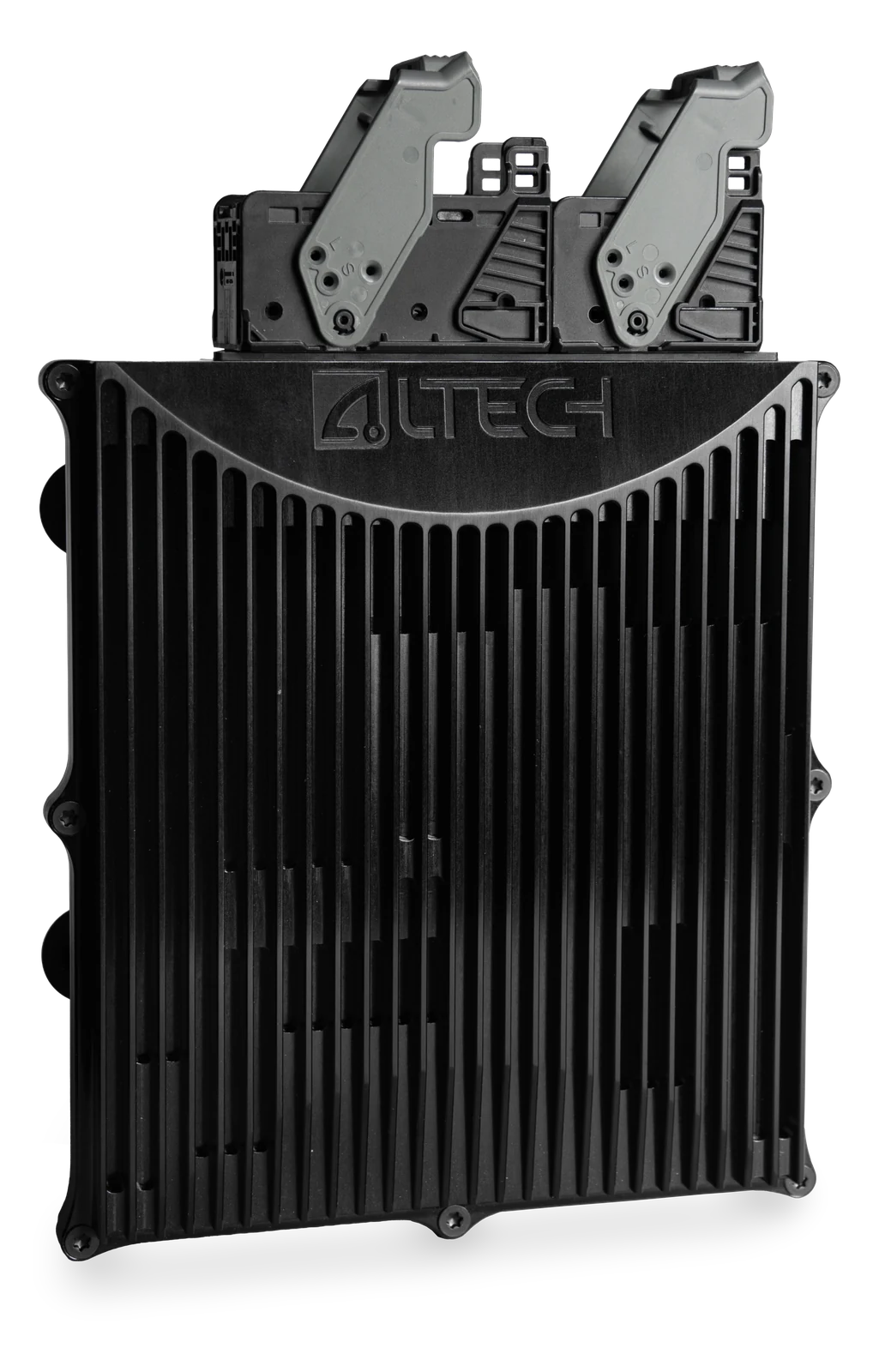
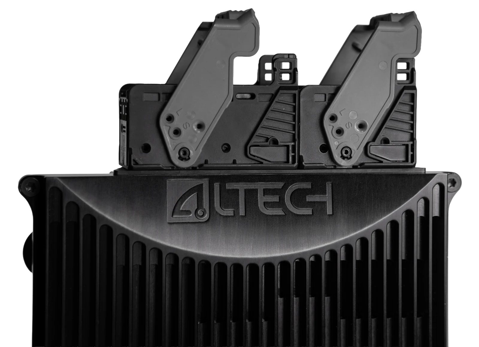
Altech control unit with the connector levers open
14
Solenoid drivers
4 × 12 A
H-bridge
3
CAN
7–32 V
Supply

Application areas

What it is used for

01

Shift and clutch control

Fourteen protected low-side drivers in four current classes for pressure and shift solenoids.

02

Actuators

Four 12 A H-bridges for shift actuators, throttle bodies and motorised valves, plus two 7.5 A high-side drivers.

03

Torque coordination

One CPU for the transmission and one for the vehicle, so torque requests and drive modes are arbitrated at the actuators.

04

Functional safety

Lockstep core, an external supervisor and safety-critical inputs on a dual ADC.

05

Vehicle dynamics

On-board accelerometer, gyroscope and barometric sensor, no extra sensors needed.

06

Network and wake

Three CAN, two LIN and two SENT channels; wakes on ignition or on CAN.

Specification

Transmission & Vehicle Control Unit

What this configuration adds to the common powertrain platform, listed further down.

Request the hardware guide
Solenoid control
14 × low-side drivers in 7.2 A, 1.75 A, 1.5 A and 0.75 A classes, PWM to 15 kHz, clamped at 30 V and short-circuit protected
Shift actuation
4 × H-bridge outputs to 12 A, 25 kHz, for shift actuators, throttle bodies and motorised valves
High-side loads
2 × high-side drivers, 7.5 A nominal, 0.009 Ω on-resistance
Spare drivers
With no injectors to drive, the 16 port-injector and 10 direct-injector channels are general-purpose outputs: low-side throughout, high-side on the direct-injector channels
Safety core
Two CPUs, one for transmission and one for vehicle control, with lockstep core execution
Supervision
External supervisor over the execution units; safety-critical analogue inputs on a dual ADC
Fluid temperature
12 × thermistor inputs for transmission fluid, oil and cooling circuits
Vehicle dynamics
On-board 3-axis accelerometer and gyroscope; barometric sensor, 40–115 kPa at ±1.0 kPa
Vehicle network
3 × CAN (ISO 11898), 2 × LIN (ISO 17987), 2 × SENT (SAE J2716); 120 Ω termination as a board option. A hardware option reconfigures four digital inputs as SENT receivers: 12 digital in and 6 SENT
Wake
Ignition (kl15) wake-up input or wake on CAN; stays operational after the input returns low

Hardware

The unit

Common powertrain platform

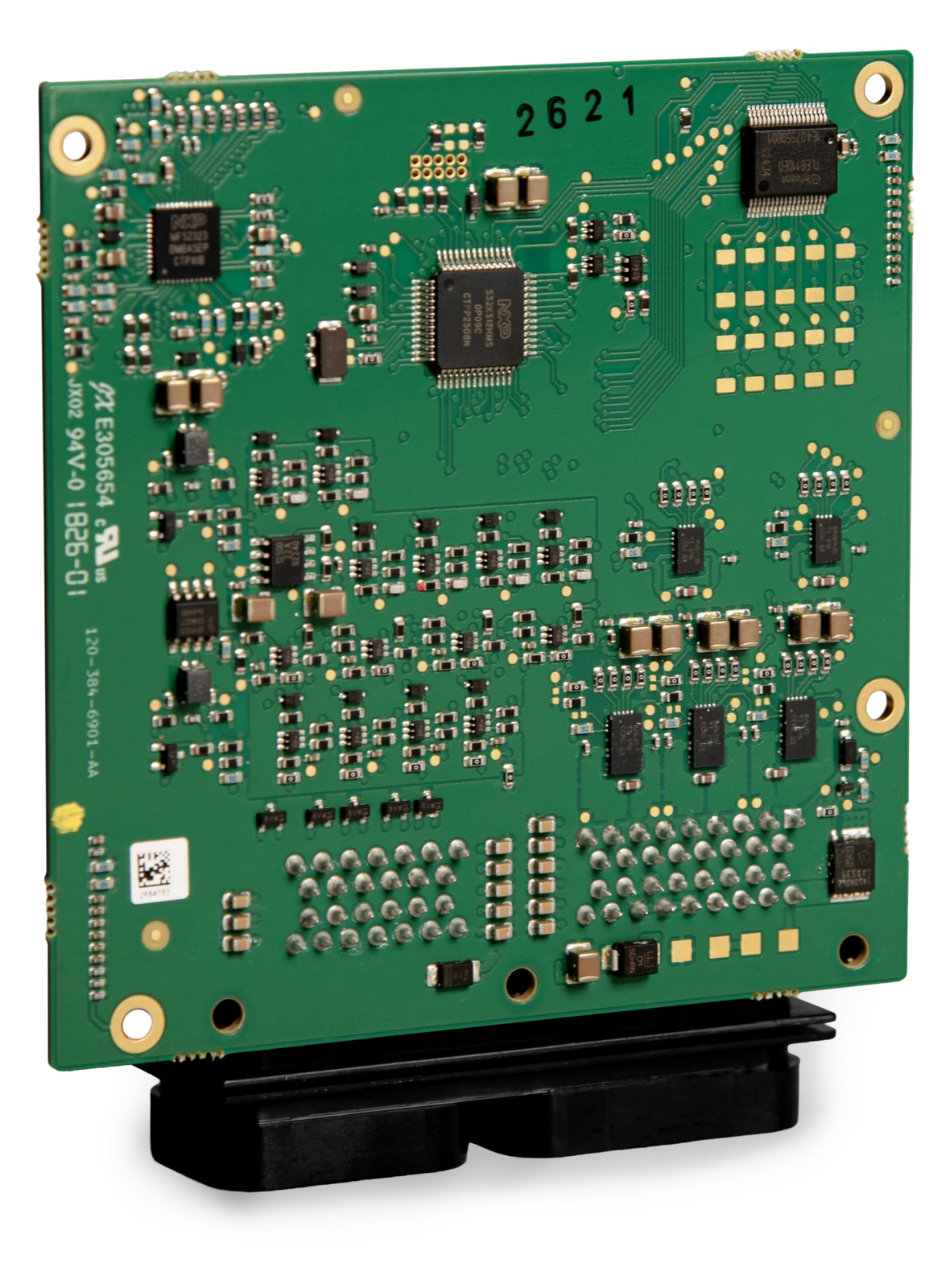
Engine, transmission and vehicle control on one board

The Engine Management System and the Transmission & Vehicle Control Unit are configurations of the same board — one toolchain, one connector, one spare part.

Processor
Automotive MCU at 264 MHz, two cores, lockstep on one
Memory
8 MB flash, 512 KB RAM
Supply
7–32 V operating, 36 V maximum; 12 V and 24 V variants configured in hardware
Connector
186-circuit Molex Compactus sealed hybrid, split 114 + 72, in 2.8 / 1.0 / 0.5 mm terminals
Sensor supply
3 × 5 V rails at 250 mA, continuously monitored by the MCU
Communication
3 × CAN, 2 × LIN, 2 × SENT. A hardware option trades four digital inputs for SENT receivers: 12 digital in and 6 SENT
Protection
Every input and output is ESD and overvoltage protected; drivers are voltage-clamped and short-circuit protected
Diagnostics
Output stages are diagnosed in hardware and report faults to the control software
Angle control
Injector, ignition and 1.75 A low-side outputs time to crank angle, as do the crank-referenced digital inputs

Included

Ships with CalTool

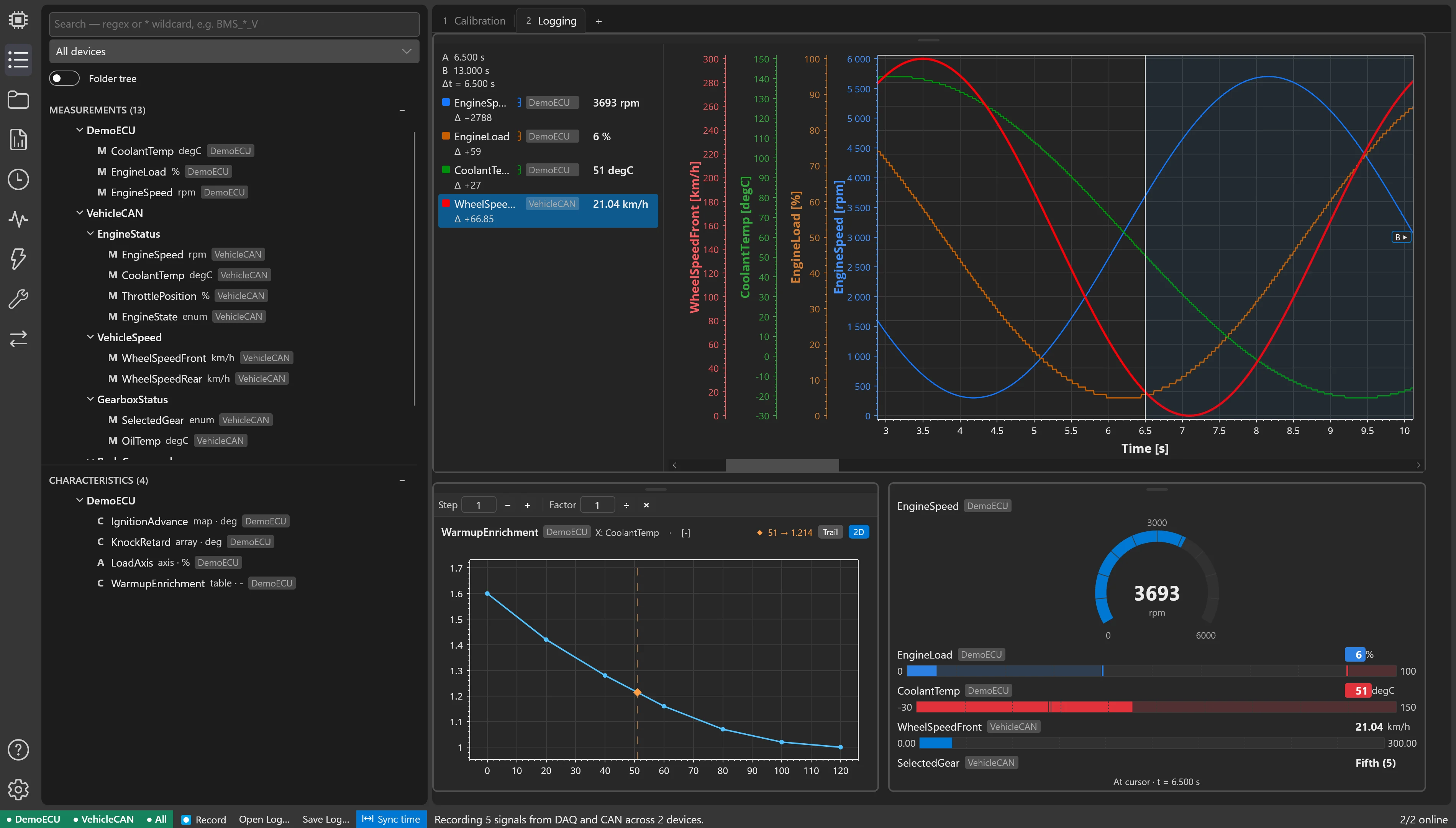
Every Transmission & Vehicle Control Unit comes with its A2L file, an XCP slave and a CalTool licence, so calibration, logging, diagnostics and flashing are covered from day one.

Get in touch

Tell us where the Transmission & Vehicle Control Unit would go

Contact us